Search VMS Institute
Esc to close ↑↓ to navigate ↵ to select
Patents & Licensing › Patents

Drawings as filed

Fourteen sheets, U.S. Application No. 19/728,053, as filed July 1, 2026. Reference numerals are retained because the specification refers to them. Click any sheet for full size.
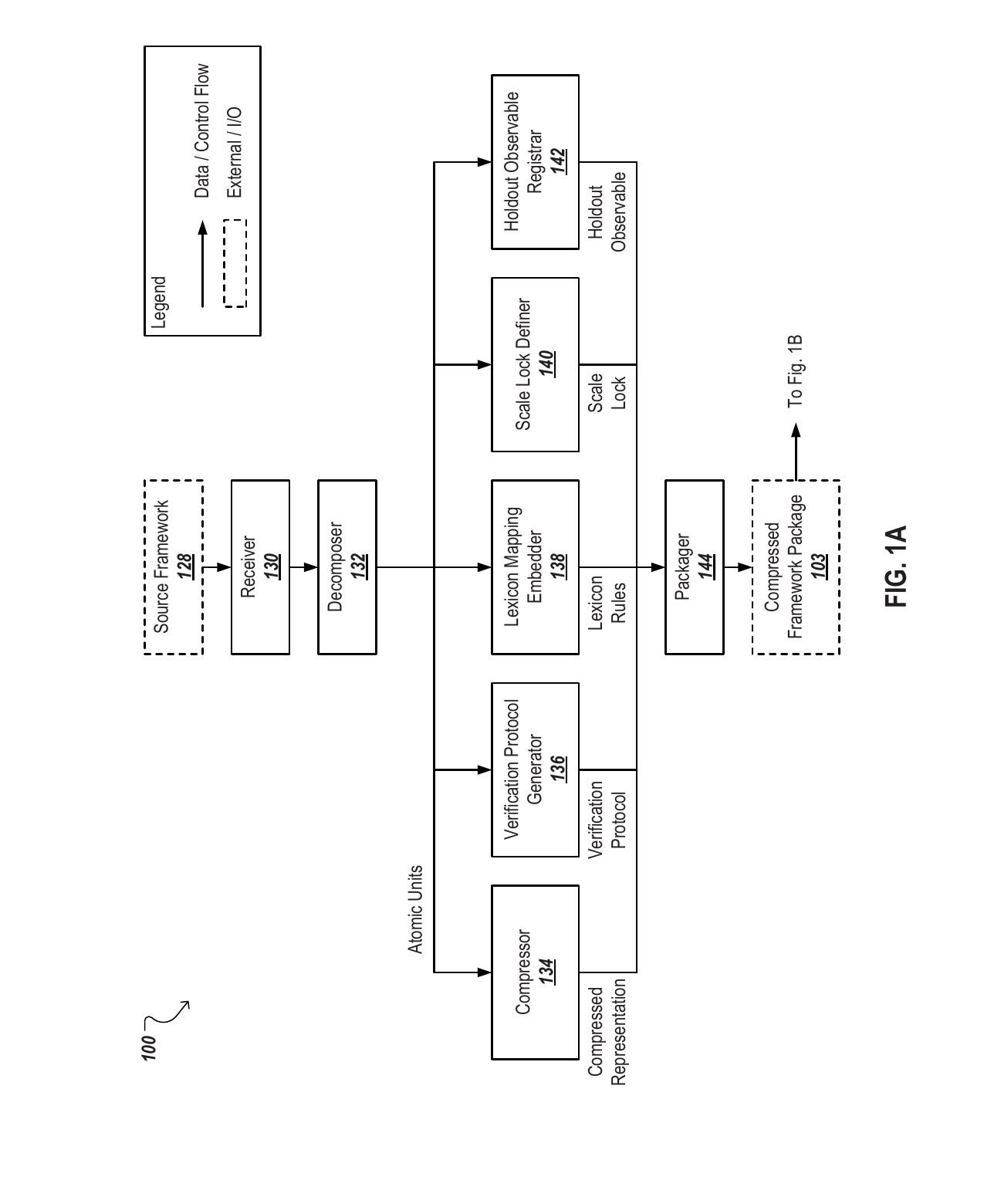
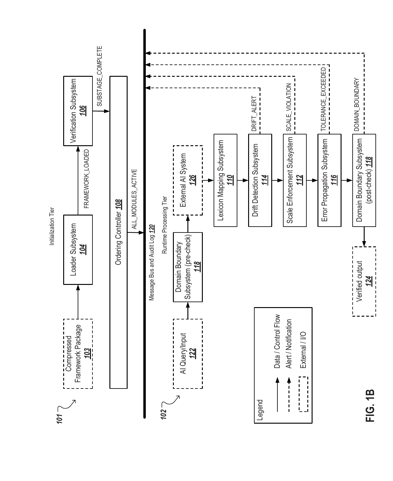
FIG. 1A
FIG. 1A is a block diagram illustrating an example preparation pipeline for processing a source framework and producing a compressed framework package.
FIG. 1B
FIG. 1B is a block diagram illustrating example initialization and runtime execution pipelines for loading and maintaining a compressed framework.
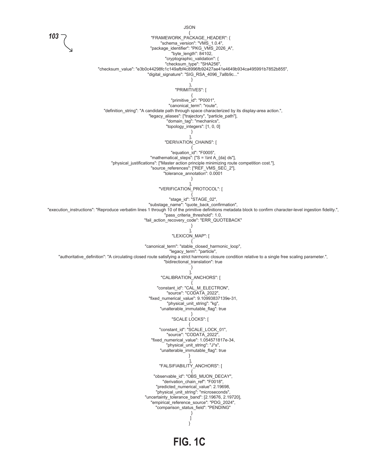
FIG. 1C
FIG. 1C shows a portion of an example compressed framework package.
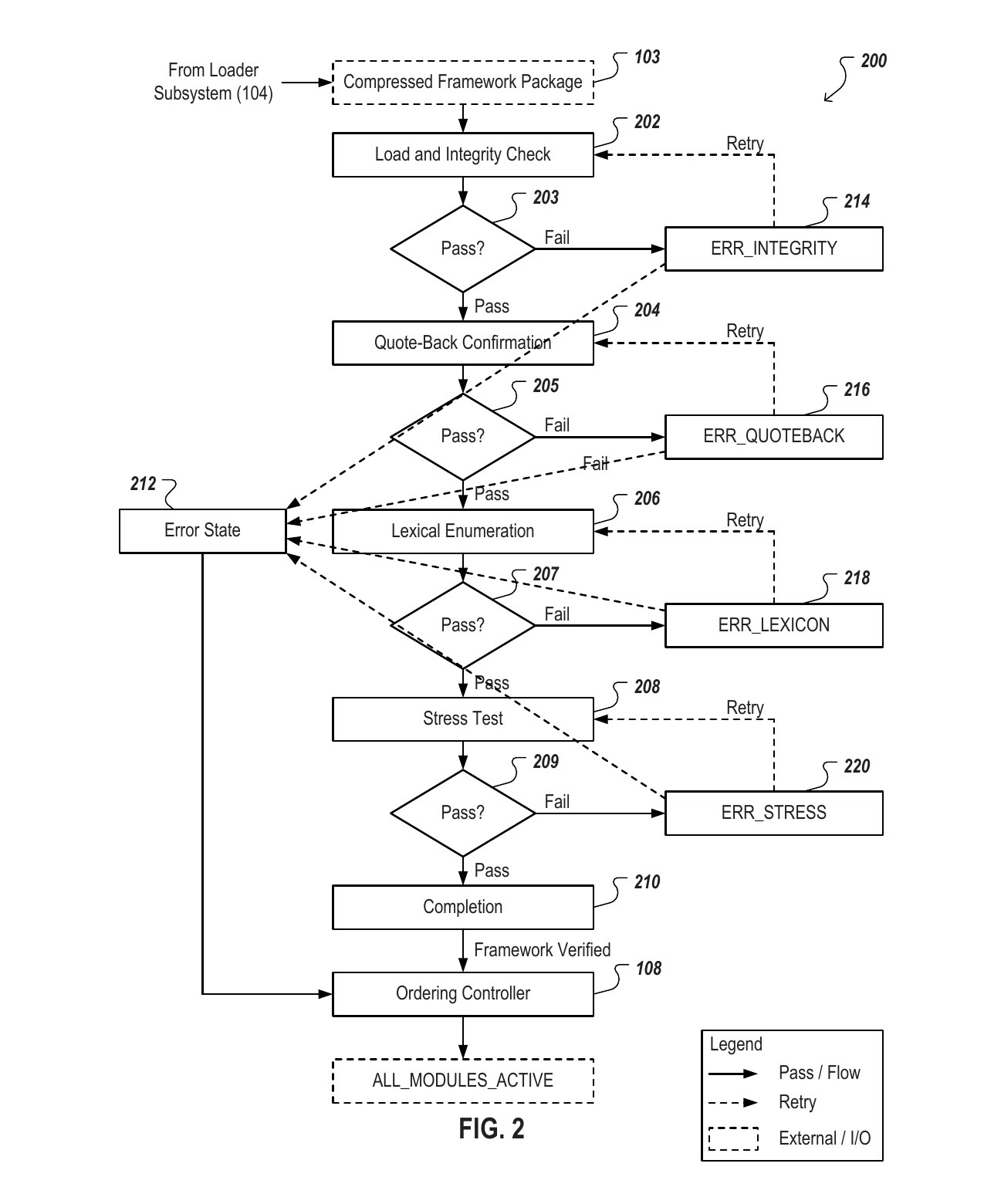
FIG. 2
FIG. 2 is a flowchart illustrating an example staged verification protocol that includes sequential validation checks and error state triggers.
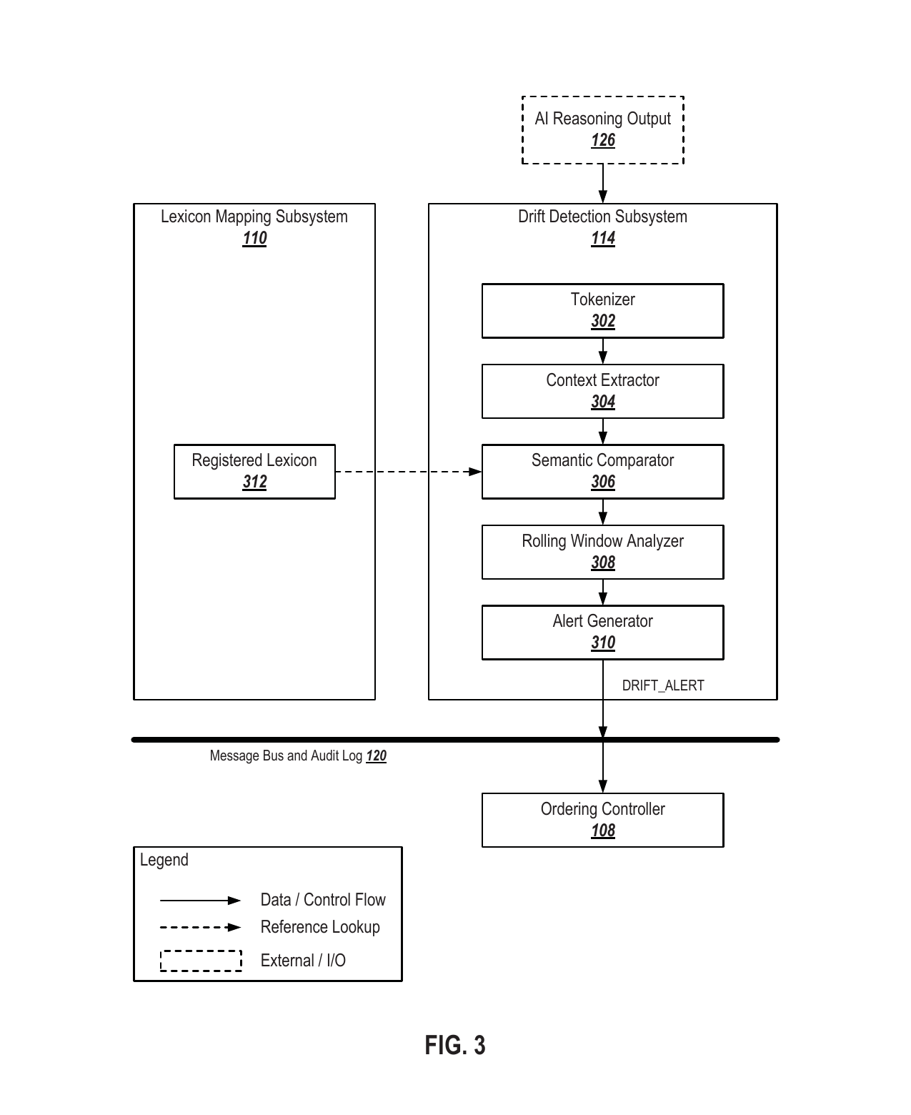
FIG. 3
FIG. 3 is a block diagram illustrating an example drift detection subsystem.
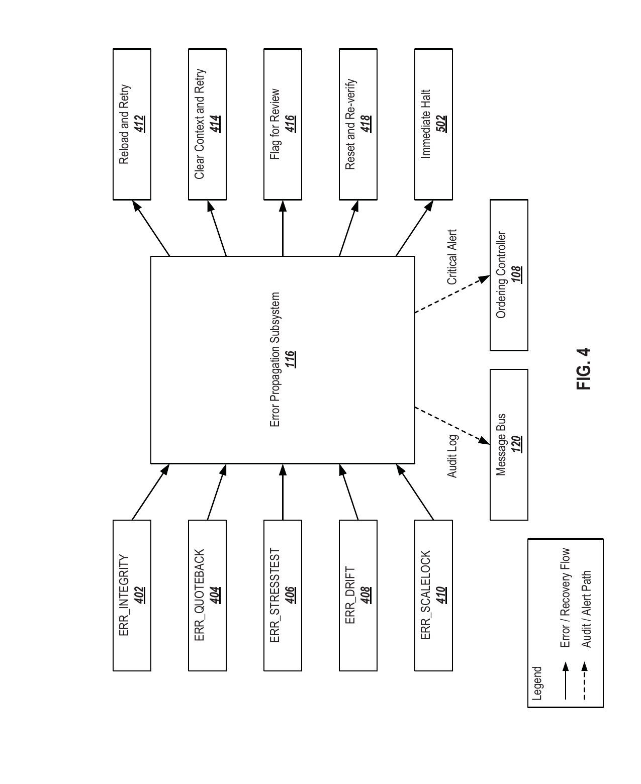
FIG. 4
FIG. 4 is a block diagram illustrating example error and recovery pathways managed by an error propagation subsystem.
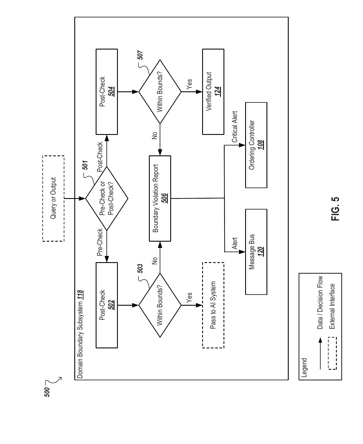
FIG. 5
FIG. 5 is a flowchart illustrating example data and decision flows of a domain boundary subsystem during pre-check and post-check filtering cycles.
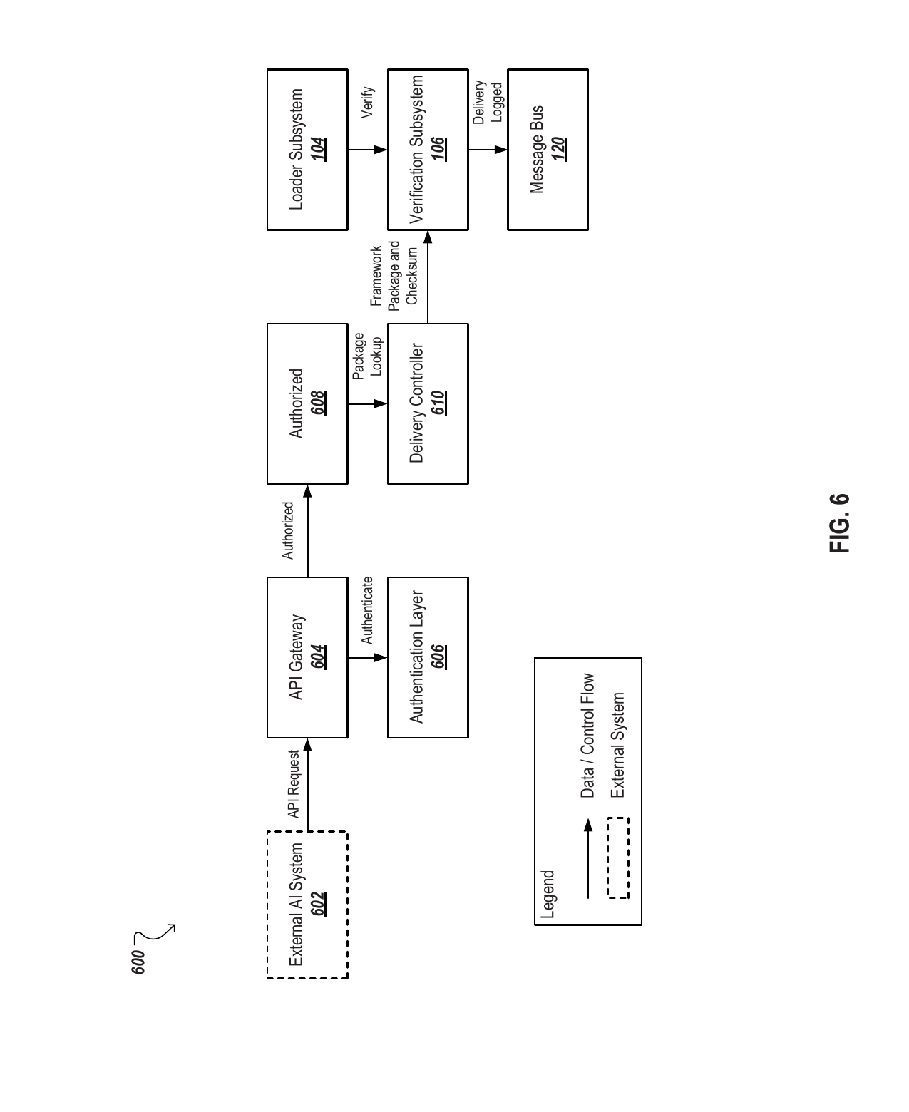
FIG. 6
FIG. 6 is a block diagram illustrating an example framework delivery architecture linking an external AI system to a local tracking infrastructure.
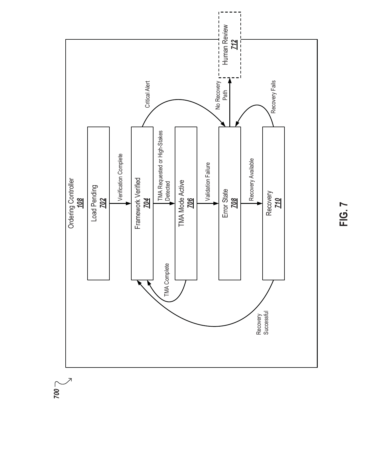
FIG. 7
FIG. 7 is a state machine diagram illustrating example operational states and recovery transitions managed by an ordering controller.
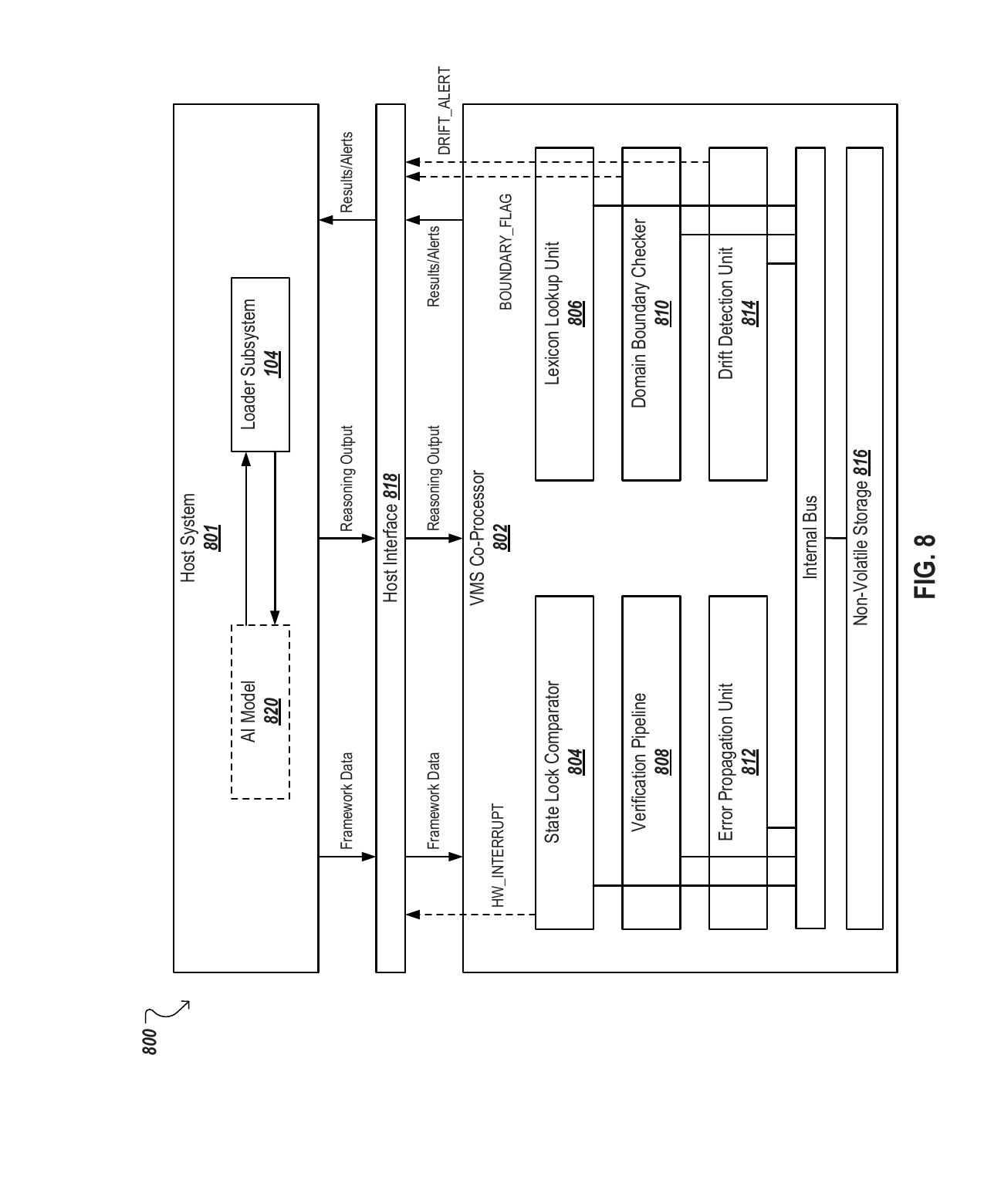
FIG. 8
FIG. 8 is a block diagram illustrating a system that includes a dedicated physical co-processor and a host system.
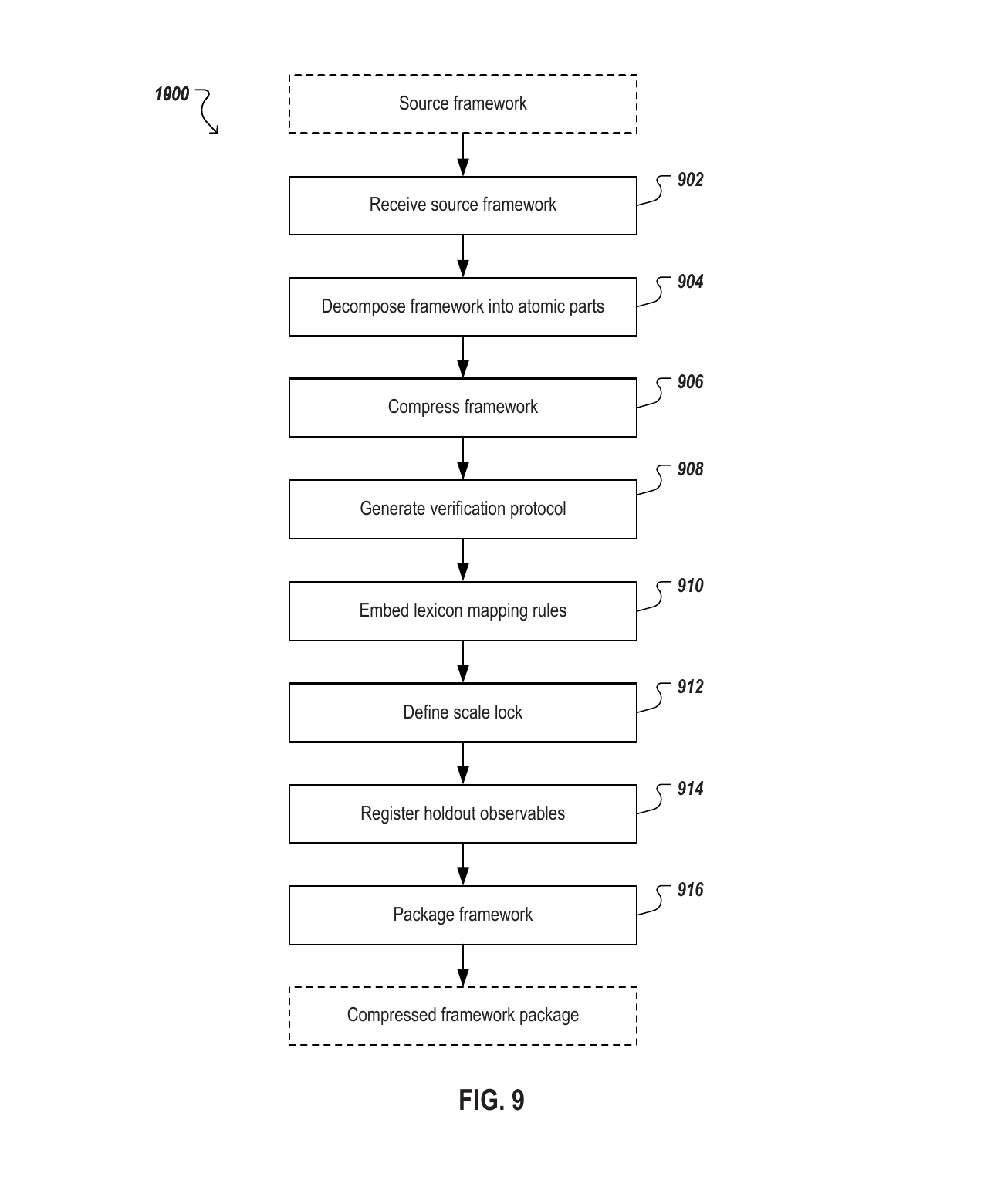
FIG. 9
FIG. 9 is a flowchart illustrating an example process for converting a source framework into a packaged compressed framework representation.
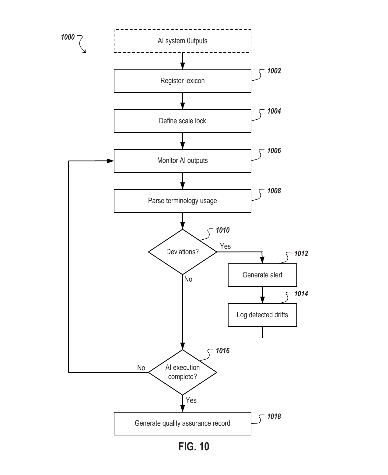
FIG. 10
FIG. 10 is a flowchart illustrating an example process for real-time monitoring and logging of continuous term usage drift.
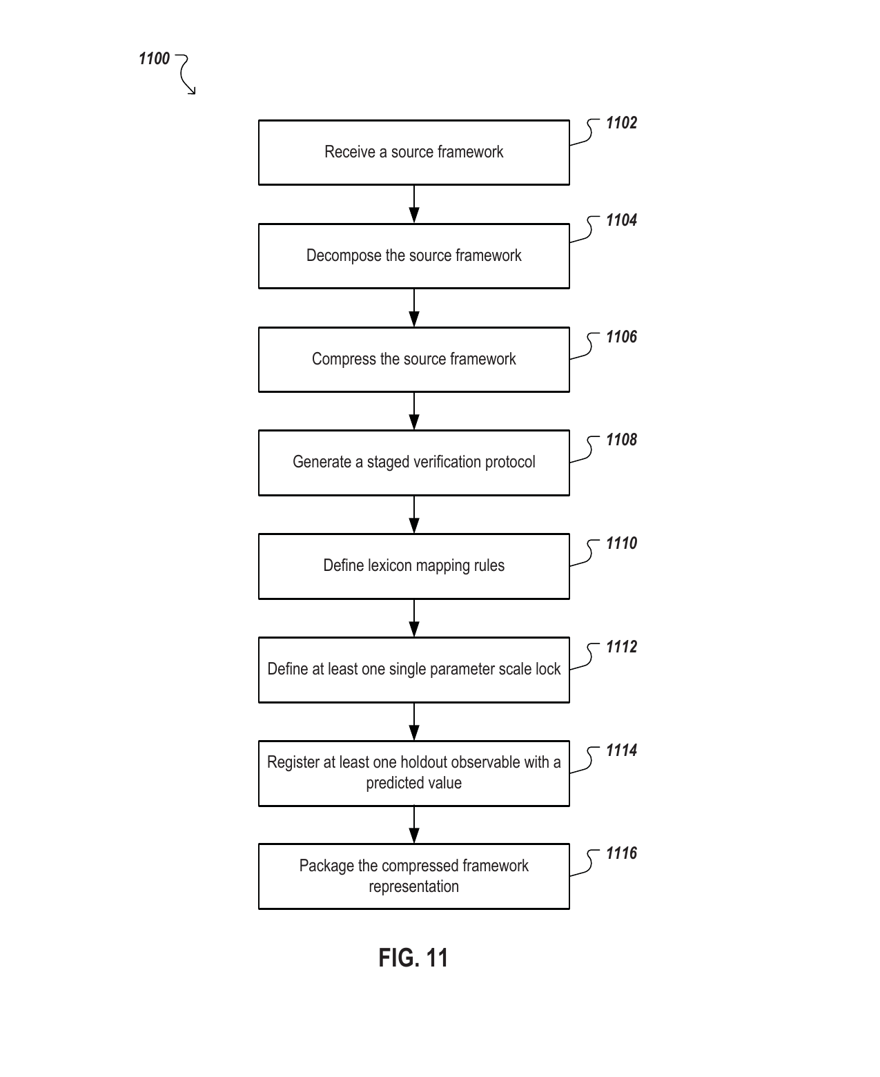
FIG. 11
FIG. 11 is a flowchart illustrating an example process for converting a source framework into a packaged compressed framework representation.
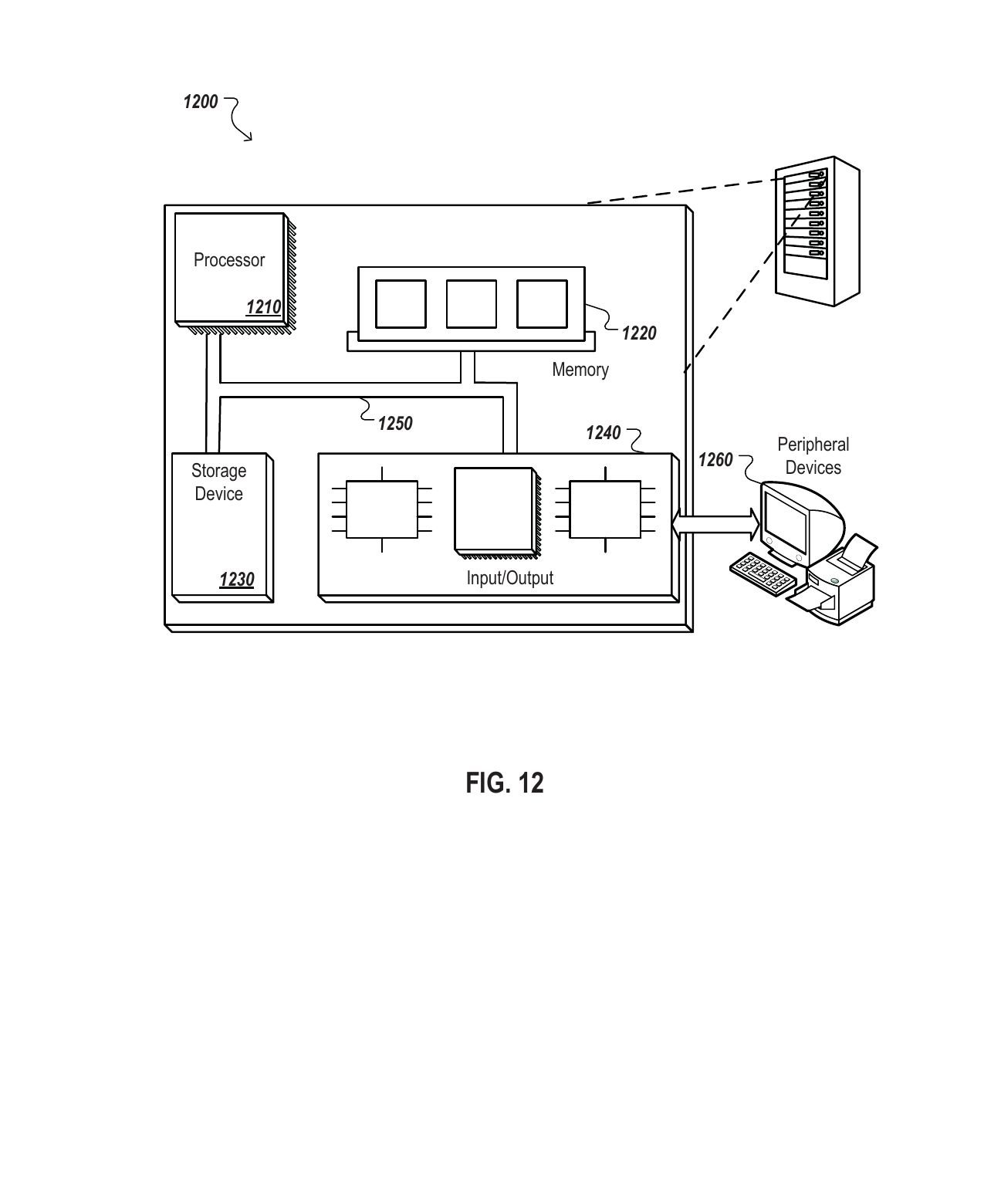
FIG. 12
FIG. 12 is a block diagram of an example computer.